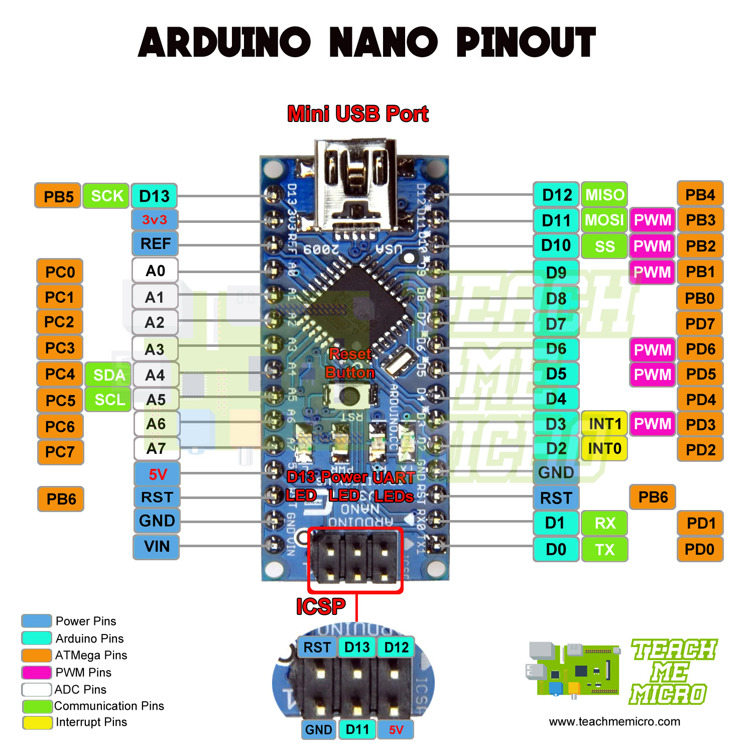

The Arduino Micro consists of 12 analog inputs, labeled as ADCX (where X is pin no.).This kind of input is usually known as digital (or binary) and these states are referred to as HIGH and LOW or 1 and 0. The Arduino Micro digital pins can read one of the two states: when the electric signal is present and when it is absent.There are 20 digital I/O pins on the Arduino Micro board that can be used as an input or output.Two ground pins are available on the Arduino Micro board. This 5V output from the voltage regulator is then connected to the 5V pin of Arduino Micro.ģ.3 V pin: The 3.3V pin generates an output voltage of 3.3v. Note: A 5-volt voltage regulator step down the input voltage coming from the Vin pin or power jack to a steady 5V. The power source of the 5V pin for the Arduino Micro board is a USB connector and the Vin. Note: Vin pin and Power jack terminal are connected to each other internally.ĥV pin: The 5V pin generates regulated 5v output for the externally connected components. When a certain voltage is given via the power jack to power the board, this voltage shows up at the Vin pin. Vin pin: It is the input voltage pin, which can be used to power up the Arduino board. What are the Power Pins on Arduino Micro? Apart from this, Arduino Micro has a reset button, 16MHz crystal oscillator, ICSP header, and a micro-USB port.Out of these 20 pins, 7 pins are PWM (Pulse Width Modulation) pins and, 12 pins are analog input pins. As shown in the Arduino micro pinout above, the board has 20 digital I/O pins.Are you a beginner? Can't decide which book to read? Check out this article on Best Arduino Books for beginners Arduino Micro Pinout The LED can be controlled by switching the pin to HIGH or LOW. TX LED (30): In the board, there is a TX LED connected to digital pin 30. RX LED (17): In the board, there is an RX LED connected to digital pin 17. INBUILT LED (13): In the Arduino Micro board, there is a built-in LED (Green) connected to the digital pin 13.
#Arduino pro micro pinout code
It’s recommended to press the reset button after flashing some code to the Arduino Micro. RESET Button: This button is used for resetting the board.
#Arduino pro micro pinout free
And once the circuit is free from overcurrent, this resettable polyfuse returns to its original state. This fuse is a resettable polyfuse that automatically breaks the connection until the short or overload is removed. It protects the computer’s USB ports from overcurrent and shorts, in case the current of more than 500 mA is drawn from the port. Note: The Arduino Micro has a fuse connected to the USB port. It is very crucial for programming the Arduino Micro board. It allows us to bridge the connection between the board and the computer. Micro USB Port: The Arduino Micro comes with a Micro USB 2.0 port. The basic function of the crystal oscillator is to provide the basic timing and control to the board. Crystal Oscillator: The Arduino Micro board comes with a crystal oscillator of frequency16MHz, which generates the clock signal in the microcontroller.


 0 kommentar(er)
